
Lenticular 3D Display: Technical Explainer
A lenticular 3D display uses a sheet of cylindrical lenses, called a lenticular lens array, mounted in front of the LCD to send different images to the left and right eye. Done well, it lets a viewer perceive real depth on a flat panel without wearing 3D glasses, a VR headset, or any other eyewear. This explainer walks through what a lenticular display actually does, where the technology sits inside 3DV’s broader spatial 3D architecture, and what to check before you decide it is right for your review workflow.
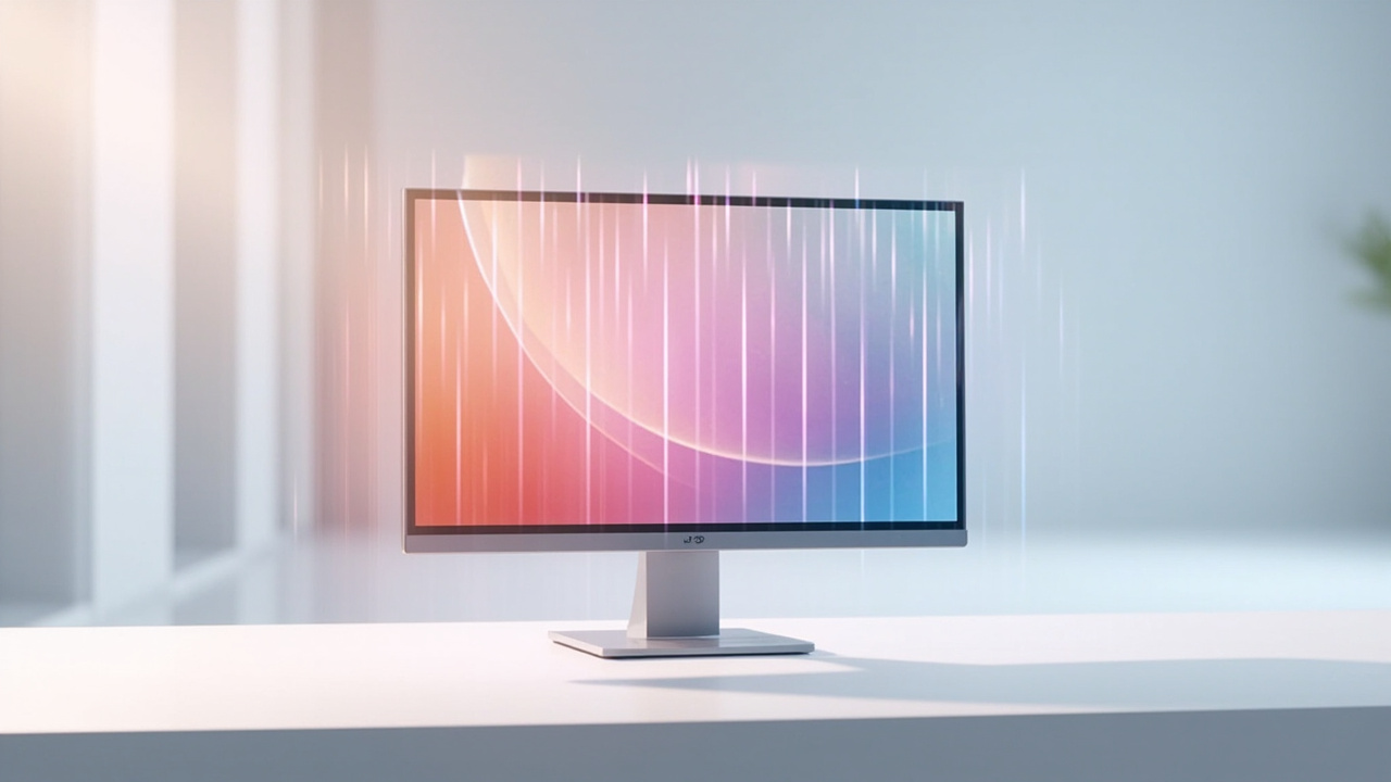
A lenticular 3D display delivers glasses-free depth through a lens array bonded in front of the LCD.
What a Lenticular 3D Display Is
A lenticular 3D display is an autostereoscopic display that achieves glasses-free 3D through an optical layer rather than through shutter glasses, polarized glasses, or a headset. The key components are:
- A high-resolution LCD panel that renders multiple sub-views underneath each lens.
- A lenticular lens array, a precision sheet of cylindrical micro-lenses bonded in front of the panel.
- A mapping and rendering stage that takes a multi-view or stereo source and assigns the right sub-pixel groups to the left-eye and right-eye slice.
- An eye-tracking stage (on 3DV Pro models) that shifts the sub-view mapping as the viewer moves, keeping the 3D image stable across a viewing zone instead of locking it to a fixed sweet spot.
The output is a monitor-style 3D review surface. Viewers sit or stand at a normal working distance, look at the screen, and see depth.
How Lenticular Optics Deliver Glasses-Free 3D
The optical core is the lenticular lens array. Each cylindrical lens on the sheet covers a vertical strip of the LCD. The lens refracts the light from that strip so that different pixels inside the strip travel toward different angles.
In a simple two-view design:
- Pixels assigned to the left-eye view are aimed at angles the left eye can see.
- Pixels assigned to the right-eye view are aimed at angles the right eye can see.
- Each lens works like a tiny projection window, fanning multiple sub-views out across a viewing zone.
In multi-view designs, the same fan of angles carries more than two sub-views spread across the zone. Movement parallax, the impression that the image shifts as the viewer moves, comes from the viewer’s eye crossing different sub-views inside that fan.
Three engineering pieces turn that optical principle into a usable display:
- Interleaving (sub-pixel mapping): the source image is sliced into vertical stripes or column groups, so that the lens can route each stripe to a different angle.
- Calibration: the lens pitch, panel pitch, and sub-pixel layout must align precisely, or the 3D effect degrades into visible banding or crosstalk.
- View mapping: on eye-tracked 3DV displays, structured-light eye tracking reports the viewer’s position, and display-side FPGA logic remaps which sub-views go where in real time, keeping both eyes inside the sweet spot.

Each lenticular lens fans multiple sub-views out across the viewing zone so the left and right eye see different images.
Where Lenticular Fits Among Autostereoscopic Methods
Autostereoscopy is the umbrella term for any display that delivers separate left- and right-eye views without glasses. Lenticular is one of the two dominant methods in commercial glasses-free panels, alongside parallax barrier displays. 3DV covers both in our explainer on autostereoscopy and our fit-for-use note on parallax barrier designs.
Compared with parallax barrier displays, lenticular displays tend to deliver:
- Higher optical brightness per sub-view, because the lens transmits light rather than blocking it, which matters in normal room lighting.
- Wider effective viewing zones when combined with eye tracking.
- More sub-views across the same panel resolution, at the cost of per-view pixel density.
The trade-off is mechanical: a lenticular array is a physical optical element that sits above the LCD, while a parallax barrier is essentially a precision mask. Both are legitimate routes into autostereoscopic 3D, but they differ in brightness, moiré risk, and how they behave under touch or cover-glass integration. Current 3DV Spatial Display models use the lenticular optical layer for these reasons.
This sits firmly inside the spatial 3D display category. If you want to compare it side by side with a classic two-view stereoscopic pipeline, the stereoscopic 3D display explainer covers the glasses-required case that lenticular technology is often positioned against.
Why 3DV Uses a Lenticular Optical Layer
Lenticular optics align with the way 3DV positions its Spatial Display line: as a glasses-free, monitor-style review surface for professional teams, not as a consumer entertainment screen.
Key reasons the lenticular layer is a fit for the architecture:
- Monitor-style workflow. Viewers do not have to put anything on. A CAD engineer, a radiologist, or a microscope reviewer can keep normal working distance and posture.
- Multi-view depth with eye tracking. Combined with structured-light eye tracking and FPGA-side view remapping, lenticular panels can keep the stereoscopic image aligned as a viewer leans or shifts.
- 2D and 3D on the same panel. Pro models switch the optical behavior between a clean 2D mode and 3D mode, so the same display can be used for everyday 2D work and dedicated 3D review.
- Compatibility with stereo-ready source content. SBS side-by-side feeds, stereo-capable CAD and medical viewers, and WebGL or game-engine pipelines can all be routed to the panel once the lenticular mapping stage is in place.
These same reasons show up in the broader spatial 3D display explainer and in the buyer-side overview on naked-eye 3d decisions.
Workflow Fit: Content, Viewing, and Room Setup
A lenticular 3D display is a review tool, not a content authoring tool. Workflow fit depends on three things: source content, viewing geometry, and room lighting.
Source content. Best results come from content that already has separate left-eye and right-eye views or can be rendered with two cameras:
- SBS (side-by-side) stereo video
- Stereo-capable CAD and 3D model viewers
- Stereo-ready medical and industrial visualization pipelines
- Unity, Unreal, WebGL, or custom 3D apps with stereo camera output
Flat 2D images, single-view 3D exports, and ordinary 2D video will display, but without the depth separation the lenticular layer is designed to route.
Viewing geometry. Define who is in front of the panel, at what distance, and for how long. For a single dedicated reviewer, a single-viewer lenticular panel with eye tracking works well. For two or three people reviewing together, a multi-view lenticular panel with a wider zone, plus good seating placement, is the usual fit. The deeper a viewing zone gets, the more sub-views the panel needs, which reduces per-view resolution.
Room setup. Bright direct light at shallow angles can pick up the lens structure. Lamps positioned overhead and slightly behind the viewer, with the screen facing away from windows, tend to give the cleanest depth image.
A lenticular 3D display fits cleanly into stereo-ready review, design, and visualization pipelines.
Limits and Trade-offs to Plan Around
Lenticular technology is mature, but it is not magic. Plan around these limits:
- Resolution per view. Each eye sees fewer pixels than the panel’s native 2D resolution. Multi-view designs split that further.
- Viewing zone borders. Outside the zone the 3D effect breaks down into reversed views or flatness. Eye tracking narrows but does not eliminate this.
- Moiré and banding risk. The lens array can interfere with the sub-pixel grid, especially under bright ambient light. Manufacturing tolerance and calibration matter.
- Touch assumptions. Current 3DV Spatial Display models are positioned as non-touch. Adding a touch layer changes the optical stack.
- Content prep overhead. Stereo or multi-view source content has to be produced in advance. Ordinary 2D assets will not suddenly become 3D.
If any of these limits are deal-breakers, the matching fit-for-use questions are below.
Compatibility Checklist for Source Content
Before you commit to a lenticular deployment, run your planned source content through this quick filter:
- Can the source output separate left and right views? SBS, multi-view, or stereo camera output: yes. Single-view 2D: no, without a re-render step.
- Is the source resolution high enough to survive sub-view splitting? A panel that resolves 4K in 2D mode will not give 4K to each eye in 3D mode.
- Does your viewer or engine support stereo output? CAD, DICOM, microscopy, and visualization tools vary in how cleanly they can hand off stereo or SBS feeds.
- How many simultaneous reviewers are in scope? One dedicated reviewer, a rotating reviewer, or a small group changes the viewing-zone requirement.
- Will the room lighting interfere? Direct light at shallow grazing angles is the usual cause of visible lens structure.
If you are unsure about any of these, the spatial 3d display software compatibility guide and the stereoscopic display software workflow guide walk through how typical content types feed into a lenticular panel.
Buyer-Fit Questions Before Deployment
Treat these as a fit-for-use checklist, not as a ranking:
- Is the workflow primarily dedicated 3D review, or is it mixed 2D and 3D on the same panel? This tends to push the choice toward Pro models.
- How many viewers need to see depth at the same time, and from what angles?
- Will the source content come from a pipeline that already supports stereo output?
- Does the room layout support the panel size and lighting conditions you are considering?
- Are you comparing against a parallax barrier alternative, a stereoscopic 3D setup with glasses, a VR headset workflow, or a light-field display? Each has different trade-offs.
If you want help mapping answers to a specific model, the 3d display screen buying guide covers screen- and form-factor-level decisions, and the Display Selector route gives a fit-for-use model recommendation. For pre-purchase technical checks, the Ask Before Ordering route is the supported way to bring your content and room details to the 3DV team.
Next Steps with 3DV
A lenticular 3D display is one of the more grounded ways to deliver glasses-free 3D on a professional review surface, and it is the optical basis 3DV uses across its Spatial Display line. When the source content, viewing zone, and room setup are aligned, the workflow is close to using a normal monitor, with real depth added.
If you are evaluating a deployment, three next steps are usually enough:
- Read the spatial 3d display explainer for the category context, then the autostereoscopy explainer for the optical framing.
- Walk your planned content through the compatibility checklist above, or use the Spatial Display Content Compatibility article and the Content-to-3D Path Checker under
/compatibility/. - Once the fit is plausible, request a demo or send your content and room notes through the Ask Before Ordering route, so the 3DV team can confirm mapping, panel choice, and viewing-zone behavior before you buy.
This article is an educational explainer. It is not a clinical or diagnostic claim, and it is not a competitor ranking. It is intended to help technical buyers, evaluation teams, and integration partners decide whether a lenticular 3D display is the right fit for their review, visualization, or training workflow.